Zilvia.net Forums | Nissan 240SX (Silvia) and Z (Fairlady) Car Forum

Go Back   Zilvia.net Forums | Nissan 240SX (Silvia) and Z (Fairlady) Car Forum > General > Tech Talk > Engine Tech

Engine Tech Technical discussion related to all relevant engines such as KA, SR, RB, CA, 2JZ , L24/26/28, VG, VQ, and LSx series.


Reply
 
Thread Tools Display Modes
Old 04-29-2015, 12:40 AM   #1
feito
Nissanaholic!
 
feito's Avatar
 
Join Date: May 2007
Location: Texas
Posts: 1,948
Trader Rating: (1)
feito has much to be proud offeito has much to be proud offeito has much to be proud offeito has much to be proud offeito has much to be proud offeito has much to be proud offeito has much to be proud offeito has much to be proud offeito has much to be proud offeito has much to be proud offeito has much to be proud of
Feedback Score: 1 reviews
RB rb25det pcv system discussion

Im trying to figure out my rb25det pcv system here and I though I make a discussion thread since I couldnt find a thread dedicated to the rb25 pcv, and the sr20 has a different system.
I really hope we can discuss our different ideas in here since I've been giving it a though for some time now.
Stock rb's come with a valve cover mounted pcv valve connected post throttle body that only opens up for crankcase gases evacuation during idle, and a ventilation port that is always flowing connected to the turbo intake, between the maf and the turbo. This is the way many cars come from the factory, including n/a ones.

IMO, this is the most optimal way to evacuate as much gases/fumes as possible from the crankcase. It creates suction in the crankcase while idling via the pcv valve port, and while underboost via the turbo intake port.
With the rb's though, im having a little trouble understanding something. Apparently rb25 heads dont have any oil galleries that allow oil and fumes to move from intake side to exhaust side and vise-versa, hence the need of a crossover hose that connects both valve covers. The problem Im seeing here is that during idle when the pcv valve is open and sucking gases and fumes (along with a little oil) it is also sucking air through the turbo intake port (clean/filtered and measured air), wasting some of its vacuum power due to the fact that this air passage is always open to flow. Fumes in the intake side VC get sucked out first, then suction continues through the crossover hose and reaches the "t" fitting on the exhaust side VC, splitting its suction power into both the exhaust side VC and the turbo intake valve cover hose. Am I making myself clear?


Am I missing something? Ive also read that the oem hose that connects the exhaust side VC fitting to the turbo intake has a restrictor in it, but im sure this is only to restrict the flow of the suction created by the turbo at higher rpm's, Im guessing that without a restrictor you could suck drops of oil and shit, which when using an operational catch can this isn't too much of an issue. But the rescrictor is no check valve, which means that some vacuum power still gets lost through it, which brings me to my next point: Why arent people using dual check valves on their rb25 pcv setups? the pcv valve and one inline with the hose that runs from the turbo intake to the exhaust side fitting? That way when the pcv valve is open and sucking up air all of its vacuum power goes towards sucking gases out of the valve covers.
Would there be anything wrong with this setup?
I am planning on running a dual catch can setup on my rb25, post throttle body and one hooked up to the turbo intake, just like from the factory.
I have done a lot of research on rb25 pcv setups and none of them seem to convince me. Here's a diagram that shows the most common setups, i will not go through the exhaust connected setups 'cause I have very little knowledge with those and am not very interested:


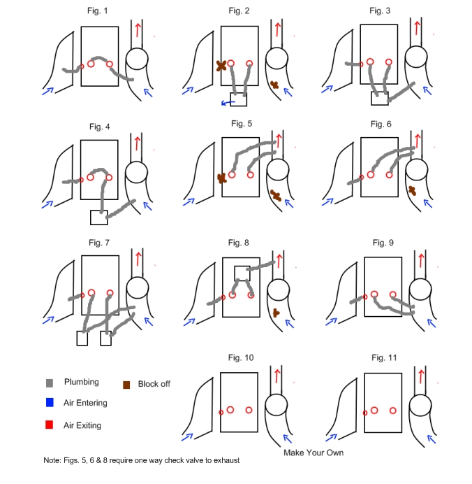
#1 is stock.
#2 is completely vented to the atmosphere, which is worse than not having neither one of the suction hoses connected since now the fumes and gases will have no help from any suction to escape the crankcase and they will only escape until the crankcase is pressurized which will hurt your gaskets causing premature leaks and may cause smoking.
#3 only filters the fumes while underboost from both VC's, and only intake side VC sees vaccum while idling.
#4 same as stock but adds some filtration while underboost.
#7 same as 3 but with two catch cans
#9 both valve covers see vaccum while under boost, only the intake side VC sees some vacuum whi idling.

Now this is what I want to do in mine: plugged the hole on the side of the intake side VC where the pcv valve grommet normally goes. Add a push-on "t" barb fitting on the upper hole on the intake side VC. Run a crossover hose from VC to VC, like the stock one. On the intake side VC, run a hose from the remaining barb connection to the catch can, then from the catch can to the catch can to a high performance check valve and finally from the check valve to a post throttle body intake port. On the exhaust side, run a hose from the remaining barb connector to a check valve, a hose from the check valve to the catch can, and finally a hose from the catch can to the turbo intake between the turbo and maf. sort of like this:


The crossover hose is very important in this case, because without it the gases/fumes located in the valve cover not seeing suction at the time (intake side if under boost, exhaust side while idling) would have to travel through the cylinder head's oil drain holes, find their way towards the opposite side through the block and finally travel up towards the valve cover seeing the suction at the time.
What do you guys think?
feito is offline   Reply With Quote
Sponsored Links
Old 04-29-2015, 07:37 AM   #2
supersayianjim
Nissanaholic!
 
supersayianjim's Avatar
 
Join Date: Jan 2010
Location: location X
Posts: 1,807
Trader Rating: (10)
supersayianjim will become famous soon enoughsupersayianjim will become famous soon enoughsupersayianjim will become famous soon enoughsupersayianjim will become famous soon enough
Feedback Score: 10 reviews
so which figure am I supposed to be using if I have 1 catch can??
supersayianjim is offline   Reply With Quote
Old 04-30-2015, 12:03 AM   #3
Kingtal0n
Post Whore!
 
Kingtal0n's Avatar
 
Join Date: Jul 2005
Location: South Florida
Age: 38
Posts: 4,649
Trader Rating: (17)
Kingtal0n has a reputation beyond reputeKingtal0n has a reputation beyond reputeKingtal0n has a reputation beyond reputeKingtal0n has a reputation beyond reputeKingtal0n has a reputation beyond reputeKingtal0n has a reputation beyond reputeKingtal0n has a reputation beyond reputeKingtal0n has a reputation beyond reputeKingtal0n has a reputation beyond reputeKingtal0n has a reputation beyond reputeKingtal0n has a reputation beyond repute
Feedback Score: 17 reviews
Send a message via AIM to Kingtal0n
You are missing the fact that below each valvecover there is the entire engine's crank case volume, think of the space between the crankshaft and the oil pan, that is also connected to both sides of the valvecover. Even if there was no "crossover" on the top they are still connected from below, which is where the combustion gasses are entering the crankcase (from below the piston rings). In other words, gasses do not escape from the combustion chamber into the space above the head, they are ejected into the area below the rings and moved upwards if there there is less pressure as intended at the baffled exits.

The ideal setup will not use a catch can at all, and has the shortest plumbing to minimize pressure drop, as well as an appropriately sized restriction on the compressor wheel side to maximize vacuum signal during boost. You can find the best size restrictor by installing a gauge that reads 0-60" water and adjust the restrictor to achieve maximum vacuum signal.
Kingtal0n is offline   Reply With Quote
Old 04-30-2015, 09:45 AM   #4
ANVIL
Zilvia FREAK!
 
ANVIL's Avatar
 
Join Date: Apr 2005
Location: Anchorage, Alaska
Posts: 1,173
Trader Rating: (8)
ANVIL can only hope to improve
Feedback Score: 8 reviews
Gonna be switching from 1 to 4 or 4 with pcv deleted/plugged.

id appreciate some input on my thread on what happened when i found my pcv faulty

http://zilvia.net/f/showthread.php?t=601919
ANVIL is offline   Reply With Quote
Old 04-30-2015, 01:13 PM   #5
feito
Nissanaholic!
 
feito's Avatar
 
Join Date: May 2007
Location: Texas
Posts: 1,948
Trader Rating: (1)
feito has much to be proud offeito has much to be proud offeito has much to be proud offeito has much to be proud offeito has much to be proud offeito has much to be proud offeito has much to be proud offeito has much to be proud offeito has much to be proud offeito has much to be proud offeito has much to be proud of
Feedback Score: 1 reviews
Quote:
Originally Posted by supersayianjim View Post
so which figure am I supposed to be using if I have 1 catch can??
if only 1 catch can is used and the car is a daily driver and is driven normal/off-boost most of the time. I would say place it between the pcv valve and the intake vacuum source since the engine will be seeing vacuum most of the time, and leave the rest of the system all stock.

Quote:
Originally Posted by Kingtal0n View Post
You are missing the fact that below each valvecover there is the entire engine's crank case volume, think of the space between the crankshaft and the oil pan, that is also connected to both sides of the valvecover. Even if there was no "crossover" on the top they are still connected from below, which is where the combustion gasses are entering the crankcase (from below the piston rings). In other words, gasses do not escape from the combustion chamber into the space above the head, they are ejected into the area below the rings and moved upwards if there there is less pressure as intended at the baffled exits.
No sir, Im not missing anything, but the point that I think you are missing, or maybe missed from my OP is that all the blow-by gasses/fumes float towards the top of the engine, the valve covers, and yes, while all the gases that are in the block crankcase while float towards the valve cover seeing suction at the time, the ones already trapped in the valve cover not seeing vacuum at the time, without a crossover hose their only escape now is to travel back down into the block crankcase and move towards the opposite side and up into the valve cover seeing the suction at the time, which 1: I dont know it it is possible or if the vacuum power is strong enough to move the gases in such a way, and 2: If the gases can't move in such a way I dont know what effect it will have in the side of the head not seeing the vacuum at the time.
Quote:
Originally Posted by Kingtal0n View Post
The ideal setup will not use a catch can at all, and has the shortest plumbing to minimize pressure drop, as well as an appropriately sized restriction on the compressor wheel side to maximize vacuum signal during boost. You can find the best size restrictor by installing a gauge that reads 0-60" water and adjust the restrictor to achieve maximum vacuum signal.
In the ideal world engines wouldnt produce blow-by, but that's not happening. Idk about you but I would like to eliminate as much contaminants off my blow-by gases.
Yes, the shortest the plumbing the better. Could you be more elaborate with the part I've highlighted?
feito is offline   Reply With Quote
Old 04-30-2015, 01:27 PM   #6
smoked240
Zilvia FREAK!
 
Join Date: Jun 2010
Location: North Dakota
Age: 30
Posts: 1,066
Trader Rating: (4)
smoked240 is not welcome here anymoresmoked240 is not welcome here anymoresmoked240 is not welcome here anymoresmoked240 is not welcome here anymoresmoked240 is not welcome here anymoresmoked240 is not welcome here anymoresmoked240 is not welcome here anymoresmoked240 is not welcome here anymoresmoked240 is not welcome here anymore
Feedback Score: 4 reviews
Send a message via MSN to smoked240
I would think best option would be both covers to a catch can and catch can to vacuum from turbo intake. Both covers are ran into the same can so no crossover should be needed. Simple, short and gets the job done. No pcv valve to go wrong. I think mishimoto makes a catch can that you can take apart and wash out.

I've even seen catch can mounted ontop the valve covers to shorten hoses.
__________________
smoked240 is offline   Reply With Quote
Old 04-30-2015, 02:29 PM   #7
feito
Nissanaholic!
 
feito's Avatar
 
Join Date: May 2007
Location: Texas
Posts: 1,948
Trader Rating: (1)
feito has much to be proud offeito has much to be proud offeito has much to be proud offeito has much to be proud offeito has much to be proud offeito has much to be proud offeito has much to be proud offeito has much to be proud offeito has much to be proud offeito has much to be proud offeito has much to be proud of
Feedback Score: 1 reviews
Quote:
Originally Posted by smoked240 View Post
I would think best option would be both covers to a catch can and catch can to vacuum from turbo intake. Both covers are ran into the same can so no crossover should be needed. Simple, short and gets the job done. No pcv valve to go wrong.
Yes, but doing it like this the crankcase will only see vacuum during boost, and nothing while idling or coasting which may have its consequences. The leaky pcv valve problem is solved by installing a high performance one.
feito is offline   Reply With Quote
Old 05-01-2015, 01:37 AM   #8
smoked240
Zilvia FREAK!
 
Join Date: Jun 2010
Location: North Dakota
Age: 30
Posts: 1,066
Trader Rating: (4)
smoked240 is not welcome here anymoresmoked240 is not welcome here anymoresmoked240 is not welcome here anymoresmoked240 is not welcome here anymoresmoked240 is not welcome here anymoresmoked240 is not welcome here anymoresmoked240 is not welcome here anymoresmoked240 is not welcome here anymoresmoked240 is not welcome here anymore
Feedback Score: 4 reviews
Send a message via MSN to smoked240
Quote:
Originally Posted by feito View Post
Yes, but doing it like this the crankcase will only see vacuum during boost, and nothing while idling or coasting which may have its consequences. The leaky pcv valve problem is solved by installing a high performance one.
Well at idle the crankcase shouldn't be producing that much pressure to cause problems or you have other things to address. The turbo is always spinning when the engine is running. Vacuum may be little at idle but shouldn't cause problems. Most setups are vent to atmo and they seem to be fine.

A lot of guys run exhaust venturi's which would be the same as running to intake before turbo technically. Since they both work off the turbo spinning. Different strokes for different folks when it comes to catch can setups.

Eliminating the pcv valve is just one less thing to worry about.

I think ideal setup would be intake cover to turbo after filter and exhaust cover to an exhaust venturi. No catch can and both valve covers should always see negative pressure. This is all theory tho, I'll hook a pressure gauge to my crank case once I get my catch can Plummed in and let you know.
__________________
smoked240 is offline   Reply With Quote
Old 05-01-2015, 11:58 AM   #9
Kingtal0n
Post Whore!
 
Kingtal0n's Avatar
 
Join Date: Jul 2005
Location: South Florida
Age: 38
Posts: 4,649
Trader Rating: (17)
Kingtal0n has a reputation beyond reputeKingtal0n has a reputation beyond reputeKingtal0n has a reputation beyond reputeKingtal0n has a reputation beyond reputeKingtal0n has a reputation beyond reputeKingtal0n has a reputation beyond reputeKingtal0n has a reputation beyond reputeKingtal0n has a reputation beyond reputeKingtal0n has a reputation beyond reputeKingtal0n has a reputation beyond reputeKingtal0n has a reputation beyond repute
Feedback Score: 17 reviews
Send a message via AIM to Kingtal0n
When you think of a crank case, think of a shell. The shell is fragile and can be broken. It also has holes for stuff to go in and out, like an isolated system working exchanging energy with the universe.

In our example, it seems to make sense to want to keep the shape of our shell circular, without much division so all parts can be treated per application easily (simplest/elegant design that meets the goal wins). That crossover tube is a simple solution to keep the shell circular, instead of divided at the top, and I never suggested you to remove it. I only mostly said to leave it stock or simulated stock (you could weld something fancy, design a custom length braided stainless hose with fancy fittings but the function will be the same) and, that it would be wise not to add length(volume) to your system, which is exactly what a catch can is.


So pressure compared to atmospheric can be measured with a variety of instruments. If you know what gradient (and units) of vacuum signal you are working with, you can fine tune pressure differential. The pressure in the compressor inlet compared to atmospheric will only start to become more of a significant vacuum if the air filter/intake begins to restrict the incoming air. As your air filter becomes more and more filthy/clogged the vacuum in front of the compressor wheel will be increasing. One way to fine tune your pcv system is to dial in the size of the plumbing/air filter such that you achieve enough of a pressure drop pre-turbo at the pcv tube to pull a reasonable suction on the crank case. Another way would be through creative plumbing, and other small details, such as the size of the restriction between the crank case and turbo inlet.

This gauge is $32 in ebay and measures in a higher resolution between atmospheric and 4"~Hg. You put a vacuum line pre-turbo and and attach it to this, then drive the car at wide open throttle and have someone record the gauge with a camera. Write down the data. Then adjust the variables and go for the best vacuum signal. You might need an even more sensitive gauge than 0-60"water, maybe even 0-15"H2O, it depends on the application, and I don't know stock numbers or I would share of course.

Details about MILJOCO LP2507L240 Pressure Gauge, 0 to 60H2O, 2-1/2In, 1/4In


You could also run a pump, either belt driven or electric. there is always some power to be gained by applying a vacuum to the crank case- the cleaner oil is just a side bonus. I like the exhaust vent idea- as long as it was baffled and oil could not get in there, I don't see any drawback with it. If your factory PCV is the intake manifold or pre-turbo, then its still going to wind up in the exhaust anyways, after it makes a pass at your turbo and engine!

Last edited by Kingtal0n; 05-01-2015 at 03:08 PM..
Kingtal0n is offline   Reply With Quote
Old 05-04-2015, 07:51 AM   #10
lgsr20swap
Zilvia Junkie
 
lgsr20swap's Avatar
 
Join Date: Nov 2008
Location: conn
Age: 40
Posts: 425
Trader Rating: (2)
lgsr20swap is an unknown quantity at this point
Feedback Score: 2 reviews
http://oilcatchcan.com/
lgsr20swap is offline   Reply With Quote
Old 05-04-2015, 10:32 PM   #11
feito
Nissanaholic!
 
feito's Avatar
 
Join Date: May 2007
Location: Texas
Posts: 1,948
Trader Rating: (1)
feito has much to be proud offeito has much to be proud offeito has much to be proud offeito has much to be proud offeito has much to be proud offeito has much to be proud offeito has much to be proud offeito has much to be proud offeito has much to be proud offeito has much to be proud offeito has much to be proud of
Feedback Score: 1 reviews
Quote:
Originally Posted by smoked240 View Post
Well at idle the crankcase shouldn't be producing that much pressure to cause problems or you have other things to address. The turbo is always spinning when the engine is running. Vacuum may be little at idle but shouldn't cause problems. Most setups are vent to atmo and they seem to be fine.

A lot of guys run exhaust venturi's which would be the same as running to intake before turbo technically. Since they both work off the turbo spinning. Different strokes for different folks when it comes to catch can setups.

Eliminating the pcv valve is just one less thing to worry about.

I think ideal setup would be intake cover to turbo after filter and exhaust cover to an exhaust venturi. No catch can and both valve covers should always see negative pressure. This is all theory tho, I'll hook a pressure gauge to my crank case once I get my catch can Plummed in and let you know.
Of course blowby during idle is much less than that under-load, but there's still some, after all lets not forget that the less load on the engine the worse the rings seal, causing more blowby. You can even find oil residue on regular cars with low miles.
Venting to atmo is ok, but not as good as adding vacuum to your crankcase at all times. And during idle there's very little to no vacuum at the turbo intake fitting unless the filter is clogged up like king said.
Running one valve cover to an exhaust venturi port and the other to the turbo intake would add vacuum to your crankcase only during under-load, while on boost, leaving us with very little to no vacuum in the crankcase during idle.
The only thing that should concern us about using a pcv valve should be the restriction, since most high performance ones wont leak.

Quote:
Originally Posted by Kingtal0n View Post
When you think of a crank case, think of a shell. The shell is fragile and can be broken. It also has holes for stuff to go in and out, like an isolated system working exchanging energy with the universe.

In our example, it seems to make sense to want to keep the shape of our shell circular, without much division so all parts can be treated per application easily (simplest/elegant design that meets the goal wins). That crossover tube is a simple solution to keep the shell circular, instead of divided at the top, and I never suggested you to remove it. I only mostly said to leave it stock or simulated stock (you could weld something fancy, design a custom length braided stainless hose with fancy fittings but the function will be the same) and, that it would be wise not to add length(volume) to your system, which is exactly what a catch can is.


So pressure compared to atmospheric can be measured with a variety of instruments. If you know what gradient (and units) of vacuum signal you are working with, you can fine tune pressure differential. The pressure in the compressor inlet compared to atmospheric will only start to become more of a significant vacuum if the air filter/intake begins to restrict the incoming air. As your air filter becomes more and more filthy/clogged the vacuum in front of the compressor wheel will be increasing. One way to fine tune your pcv system is to dial in the size of the plumbing/air filter such that you achieve enough of a pressure drop pre-turbo at the pcv tube to pull a reasonable suction on the crank case. Another way would be through creative plumbing, and other small details, such as the size of the restriction between the crank case and turbo inlet.

This gauge is $32 in ebay and measures in a higher resolution between atmospheric and 4"~Hg. You put a vacuum line pre-turbo and and attach it to this, then drive the car at wide open throttle and have someone record the gauge with a camera. Write down the data. Then adjust the variables and go for the best vacuum signal. You might need an even more sensitive gauge than 0-60"water, maybe even 0-15"H2O, it depends on the application, and I don't know stock numbers or I would share of course.

Details about MILJOCO LP2507L240 Pressure Gauge, 0 to 60H2O, 2-1/2In, 1/4In


You could also run a pump, either belt driven or electric. there is always some power to be gained by applying a vacuum to the crank case- the cleaner oil is just a side bonus. I like the exhaust vent idea- as long as it was baffled and oil could not get in there, I don't see any drawback with it. If your factory PCV is the intake manifold or pre-turbo, then its still going to wind up in the exhaust anyways, after it makes a pass at your turbo and engine!
which is exactly why we like to add catch cans, even if it means that we have to sacrifice pressure drop by adding some volume.
No, I wont waste my money on fancy braided stainless steel hoses...
Lots of good info in there, especially the measuring info. Im still doing a lot of reading on other pcv setups. Let me ask you, how do you think it would affect the system to have two pcv valves? Adding an extra one on the breather to turbo intake hose.


Quote:
Originally Posted by lgsr20swap View Post
thanks, but those are just basics sir.
feito is offline   Reply With Quote
Old 05-05-2015, 04:16 PM   #12
smoked240
Zilvia FREAK!
 
Join Date: Jun 2010
Location: North Dakota
Age: 30
Posts: 1,066
Trader Rating: (4)
smoked240 is not welcome here anymoresmoked240 is not welcome here anymoresmoked240 is not welcome here anymoresmoked240 is not welcome here anymoresmoked240 is not welcome here anymoresmoked240 is not welcome here anymoresmoked240 is not welcome here anymoresmoked240 is not welcome here anymoresmoked240 is not welcome here anymore
Feedback Score: 4 reviews
Send a message via MSN to smoked240
Very helpful info!! I'll probably install a pcv valve now. Any recommendations on a good one? Running rb26 covers. Currently have only an fittings pressed in, the catch can is the last piece to fire my build
__________________
smoked240 is offline   Reply With Quote
Old 05-06-2015, 09:48 AM   #13
lgsr20swap
Zilvia Junkie
 
lgsr20swap's Avatar
 
Join Date: Nov 2008
Location: conn
Age: 40
Posts: 425
Trader Rating: (2)
lgsr20swap is an unknown quantity at this point
Feedback Score: 2 reviews
I added that becouse this will probably come up in a google search and if no one actually knows how and what a pcv valve does and work they will after reading that article and have a better understanding on what they r reading here
lgsr20swap is offline   Reply With Quote
Old 05-06-2015, 10:43 AM   #14
Kingtal0n
Post Whore!
 
Kingtal0n's Avatar
 
Join Date: Jul 2005
Location: South Florida
Age: 38
Posts: 4,649
Trader Rating: (17)
Kingtal0n has a reputation beyond reputeKingtal0n has a reputation beyond reputeKingtal0n has a reputation beyond reputeKingtal0n has a reputation beyond reputeKingtal0n has a reputation beyond reputeKingtal0n has a reputation beyond reputeKingtal0n has a reputation beyond reputeKingtal0n has a reputation beyond reputeKingtal0n has a reputation beyond reputeKingtal0n has a reputation beyond reputeKingtal0n has a reputation beyond repute
Feedback Score: 17 reviews
Send a message via AIM to Kingtal0n
Have you ever put your finger over the "breather hose on the turbo intake" while the engine runs?

I am afraid a 1-way check valve on this side might damage the engine's oil seals.
The 1-way valve is "only" for preventing boost pressure from entering the engine's crankcase. Since there is no boost pressure on that side... it makes little sense to use one there.
Kingtal0n is offline   Reply With Quote
Old 05-06-2015, 01:37 PM   #15
feito
Nissanaholic!
 
feito's Avatar
 
Join Date: May 2007
Location: Texas
Posts: 1,948
Trader Rating: (1)
feito has much to be proud offeito has much to be proud offeito has much to be proud offeito has much to be proud offeito has much to be proud offeito has much to be proud offeito has much to be proud offeito has much to be proud offeito has much to be proud offeito has much to be proud offeito has much to be proud of
Feedback Score: 1 reviews
Quote:
Originally Posted by Kingtal0n View Post
Have you ever put your finger over the "breather hose on the turbo intake" while the engine runs?

I am afraid a 1-way check valve on this side might damage the engine's oil seals.
The 1-way valve is "only" for preventing boost pressure from entering the engine's crankcase. Since there is no boost pressure on that side... it makes little sense to use one there.
Im sure that either u didnt read my op throughoughly, or i wasnt clear enough, which i understand since english is not my first language and putting this idea into words is not the simplest thing to do. My theory is that by addind a check valve on the turbo intake side, the pcv valve will be able to keep higher vacuum levels while idling, no vacuum power will be lost throught the turbo intake side. The turbo intake side check valve will open while underboost, when the turbo is really creating some suction and the pcv valve is closed. I dont see how it could damaged the engine oil seals, we both have agreed before that the turbo creates very little to no vacuum on the intake pipe while idling, it would make no diference.
feito is offline   Reply With Quote
Old 05-06-2015, 06:00 PM   #16
Kingtal0n
Post Whore!
 
Kingtal0n's Avatar
 
Join Date: Jul 2005
Location: South Florida
Age: 38
Posts: 4,649
Trader Rating: (17)
Kingtal0n has a reputation beyond reputeKingtal0n has a reputation beyond reputeKingtal0n has a reputation beyond reputeKingtal0n has a reputation beyond reputeKingtal0n has a reputation beyond reputeKingtal0n has a reputation beyond reputeKingtal0n has a reputation beyond reputeKingtal0n has a reputation beyond reputeKingtal0n has a reputation beyond reputeKingtal0n has a reputation beyond reputeKingtal0n has a reputation beyond repute
Feedback Score: 17 reviews
Send a message via AIM to Kingtal0n
Quote:
Originally Posted by feito View Post
Im sure that either u didnt read my op throughoughly, or i wasnt clear enough, which i understand since english is not my first language and putting this idea into words is not the simplest thing to do. My theory is that by addind a check valve on the turbo intake side, the pcv valve will be able to keep higher vacuum levels while idling, no vacuum power will be lost throught the turbo intake side. The turbo intake side check valve will open while underboost, when the turbo is really creating some suction and the pcv valve is closed. I dont see how it could damaged the engine oil seals, we both have agreed before that the turbo creates very little to no vacuum on the intake pipe while idling, it would make no diference.
put your finger over the valvecover port while the engine is idling. the vacuum in the crankcase will escalate from something close to atmospheric- perhaps 35" H2O... to well over 100" H2O (if your engine is actually sealed up the way it should be), I don't know how much higher it might go, but it might be enough to pull the seals into the engine.

the blow-by oil mess splashing everywhere is mostly the issue for wide open throttle engine, attempting a maximum power run, but no engine produces idle vacuum at wide open throttle, and at engine idle even with a significant blow-by the OEM baffle should still be able to handle the mess.


Lets go back to reasons for why we are doing what we are doing. I do not want a strong vacuum in my engine at idle because even if my seals are up to the challenge all I really get out of it is extra oil vapor in my intake manifold, I would have to guess that the OEM manufacturer was thinking along the same lines(unwanted item), either that or pcv valves are very expensive.
__________________
5.3/4l80e/turbo 240sx playthrough:
https://tinyurl.com/turbo240
Kingtal0n is offline   Reply With Quote
Old 05-06-2015, 06:32 PM   #17
feito
Nissanaholic!
 
feito's Avatar
 
Join Date: May 2007
Location: Texas
Posts: 1,948
Trader Rating: (1)
feito has much to be proud offeito has much to be proud offeito has much to be proud offeito has much to be proud offeito has much to be proud offeito has much to be proud offeito has much to be proud offeito has much to be proud offeito has much to be proud offeito has much to be proud offeito has much to be proud of
Feedback Score: 1 reviews
Quote:
Originally Posted by Kingtal0n View Post
put your finger over the valvecover port while the engine is idling. the vacuum in the crankcase will escalate from something close to atmospheric- perhaps 35" H2O... to well over 100" H2O (if your engine is actually sealed up the way it should be), I don't know how much higher it might go, but it might be enough to pull the seals into the engine.
Ahhh, ok, i see. I never though the intake manifold could create too much vacuum at idle to try to pull in the gaskets. So, is the vacuum/suction created by the turbo at the intake pipe under full boost much less than that created by the intake manifold at idle? Because during wot, when the turbo intake is doing all the suction, there's no other opening in the crankcase, pcv valve is shut, and we're not messing up our gaskets having them sucked into the engine. Unless all the extra blow-by created at wot compensates for all the extra vacuum.
Quote:
Originally Posted by Kingtal0n View Post
Lets go back to reasons for why we are doing what we are doing. I do not want a strong vacuum in my engine at idle because even if my seals are up to the challenge all I really get out of it is extra oil vapor in my intake manifold, I would have to guess that the OEM manufacturer was thinking the same thing, either that or pcv valves are very expensive.
manufactures holding back on a superior design because of a few dollars hahaha. Reason why im giving it too much though on this is because im afraid the exhaust side valve cover isnt seeing too much vacuum at idle, since the crossover hose shares the same valve cover fitting with the turbo intake hose, and I fear most of the suction from the crossover hose may be wasted at the turbo intake hose... am I making myself clear?
feito is offline   Reply With Quote
Old 05-08-2015, 09:20 AM   #18
Kingtal0n
Post Whore!
 
Kingtal0n's Avatar
 
Join Date: Jul 2005
Location: South Florida
Age: 38
Posts: 4,649
Trader Rating: (17)
Kingtal0n has a reputation beyond reputeKingtal0n has a reputation beyond reputeKingtal0n has a reputation beyond reputeKingtal0n has a reputation beyond reputeKingtal0n has a reputation beyond reputeKingtal0n has a reputation beyond reputeKingtal0n has a reputation beyond reputeKingtal0n has a reputation beyond reputeKingtal0n has a reputation beyond reputeKingtal0n has a reputation beyond reputeKingtal0n has a reputation beyond repute
Feedback Score: 17 reviews
Send a message via AIM to Kingtal0n
Quote:
Originally Posted by feito View Post
So, is the vacuum/suction created by the turbo at the intake pipe under full boost much less than that created by the intake manifold at idle?
I feel like you would be lucky to see 1" of Hg at the turbo inlet (compared to 15" Hg at intake manifold idle) with a clean free flowing air filter. remember as the air filter/plumbing becomes restrictive this number changes. If your turbo supports 500bhp and you try to make 500bhp but the air filter only supports 200bhp you can imagine there will be a much stronger vacuum in front of the wheel (and less power than anticipated).


Quote:
Unless all the extra blow-by created at wot compensates for all the extra vacuum.
This is also an issue. The more the rings let by, more suction volume will be necessary to keep the crank case in a state of vacuum. Chances are, on an old engine, there is no crank case ventilation achieved by any factory PCV because of all the additional blow-by. again, you need to install an actual gauge and take a recording of it to be sure what you are getting.


Quote:
im afraid the exhaust side valve cover isnt seeing too much vacuum at idle, since the crossover hose shares the same valve cover fitting with the turbo intake hose, and I fear most of the suction from the crossover hose may be wasted at the turbo intake hose... am I making myself clear?
Perhaps a differential equation would help. If you install several gauges at each gradient; 1 per valve cover, 1 in the center cross over, 1 at the pcv ports, 1 in the oil pan (above the oil), you will find that pressure is variable everywhere, even if only by a tenth or thousandth of an inch of water. The rate of change of a pressure drop depends on many variables; source, distance, gas composition, temperature, and will vary engine to engine because of these sizes/materials which is why there is no perfect answer. Two engines with identical setups can supply completely different vacuum signal gradients during wide open throttle because one has a more filthy air cleaner. If the source vacuum variable is held still, lets hold it at 1" Hg, What would the differential be across the engine? I would expect something like .99" at the pcv port, .975" in that valvecover, .9537" in the cross over, .9485" in the other valve cover, .9333" in the oil pan.
You would need some very sensitive sensors, with a recording mechanism, to be able to tell the difference. I am not suggesting you do this, it is only an example.

If you blocked off the crossover you might lower the vacuum signal in the other valve cover by about .0250" as a guess, while it will increase slightly in the oil pan. Technically this is a more ideal situation, since you are trying to get the vacuum best right under the piston rings (blow-by does not come out of the head, into the valve cover, after all). There may be other unintended consequences however, maybe the valvecover gasket on the intake side is at risk without the crossover (if the ports in the head that lead to the crankcase are not large enough or if oil is puddled in them at the time, a high vacuum might result in that one valve cover, and ruin the gasket), so that crossover is like OEM insurance that pressure will be somewhat divided equally throughout the crankcase.
__________________
5.3/4l80e/turbo 240sx playthrough:
https://tinyurl.com/turbo240
Kingtal0n is offline   Reply With Quote
Old 10-26-2015, 09:28 PM   #19
feito
Nissanaholic!
 
feito's Avatar
 
Join Date: May 2007
Location: Texas
Posts: 1,948
Trader Rating: (1)
feito has much to be proud offeito has much to be proud offeito has much to be proud offeito has much to be proud offeito has much to be proud offeito has much to be proud offeito has much to be proud offeito has much to be proud offeito has much to be proud offeito has much to be proud offeito has much to be proud of
Feedback Score: 1 reviews
I've given it some though, and this is what I've come up with so far.

I wanted to have both cans in a single unit, but I couldnt find where to put it where the hoses wouldnt be too long. The under-load one will be sitting right next to the radiator. The idle one will be sitting right next to the intake manifold by the strut tower. The factory port for the pcv valve on the side of the passenger side VC will be blocked, obviously. I could always add a restrictor between the under-load catch can outlet and the turbo inlet later down the road. I would have to get the gauges and take some reading like kingtalon said, and choose the right size restrictor if the 3/8 plumbing is still too large for the idle vacuum to create enough suction in the crankcase. I am also considering installing a crossover at the very back of the VC's, a la 26.
So, this will be basically a very similar to factory setup.

Catch cans are from saikou michi. They are actually baffled, are custom made to order with your own specifications, and their customer service is on point. Here's their website:
http://www.saikoumichi.com/general_product_list.html

The check valve I actually had a little trouble finding it. Most check valves I came across are meant for liquid and require a much higher pressure to crack open, no bueno for a pcv setup. I stumble upon this website in a srt4 forum after a few hours of research. They claim to have an opening pressure of only .25 psi and can hold up to 100psi when closed, made of aluminum and at an affordable price, I was sold. I actually ordered two, an extra one for the brake booster hose. I tested them at work, with only 25psi, but not a single bubble underwater, me likey. Here's their website:
https://www.extremepsi.com/store/pro...cat=308&page=1
feito is offline   Reply With Quote
Old 10-27-2015, 05:46 PM   #20
supersayianjim
Nissanaholic!
 
supersayianjim's Avatar
 
Join Date: Jan 2010
Location: location X
Posts: 1,807
Trader Rating: (10)
supersayianjim will become famous soon enoughsupersayianjim will become famous soon enoughsupersayianjim will become famous soon enoughsupersayianjim will become famous soon enough
Feedback Score: 10 reviews
updates?.......................................... .........
supersayianjim is offline   Reply With Quote
Old 10-29-2015, 09:43 PM   #21
feito
Nissanaholic!
 
feito's Avatar
 
Join Date: May 2007
Location: Texas
Posts: 1,948
Trader Rating: (1)
feito has much to be proud offeito has much to be proud offeito has much to be proud offeito has much to be proud offeito has much to be proud offeito has much to be proud offeito has much to be proud offeito has much to be proud offeito has much to be proud offeito has much to be proud offeito has much to be proud of
Feedback Score: 1 reviews
excuse all the dirt. I havent work on it much and it's been accumulating dust and dirt...
Anyway. Here's how my setup is gonna be. I'll be building brackets for them next and adding clamps. Note the 3/8 hose on the CC on the turbo side? It will connect to a turbo inlet pipe connection which I'll be welding on the lower area of the pipe, so basically it'll look the same. The pcv hole on the side of the passenger side valve cover will be plugged.
It might not look the nicest, but keeping the hoses short is very important in order to minimize pressure drop.


feito is offline   Reply With Quote
Old 10-29-2015, 10:35 PM   #22
Kingtal0n
Post Whore!
 
Kingtal0n's Avatar
 
Join Date: Jul 2005
Location: South Florida
Age: 38
Posts: 4,649
Trader Rating: (17)
Kingtal0n has a reputation beyond reputeKingtal0n has a reputation beyond reputeKingtal0n has a reputation beyond reputeKingtal0n has a reputation beyond reputeKingtal0n has a reputation beyond reputeKingtal0n has a reputation beyond reputeKingtal0n has a reputation beyond reputeKingtal0n has a reputation beyond reputeKingtal0n has a reputation beyond reputeKingtal0n has a reputation beyond reputeKingtal0n has a reputation beyond repute
Feedback Score: 17 reviews
Send a message via AIM to Kingtal0n
This is the OEM way, this is the way I run my PCV, if I do not have a belt driven vacuum pump or dry sump.


Heres my bypass, the way we need to run our bypass on the hot-side as close to the compressor as possible
Kingtal0n is offline   Reply With Quote
Old 10-29-2015, 10:45 PM   #23
feito
Nissanaholic!
 
feito's Avatar
 
Join Date: May 2007
Location: Texas
Posts: 1,948
Trader Rating: (1)
feito has much to be proud offeito has much to be proud offeito has much to be proud offeito has much to be proud offeito has much to be proud offeito has much to be proud offeito has much to be proud offeito has much to be proud offeito has much to be proud offeito has much to be proud offeito has much to be proud of
Feedback Score: 1 reviews
yeah. Like I said, mine will be similar to oem, plus two catch cans. My BPV is also similar to yours, you can see it right next to the maf on the hot pipe. I am also thinking more and more on adding those crossover connections at the back of the VC. Also, that diagram you provided shows the crankcase ventilation flow during idle only. You may want to clarify that before some people get confused.
feito is offline   Reply With Quote
Old 10-30-2015, 12:24 AM   #24
Kingtal0n
Post Whore!
 
Kingtal0n's Avatar
 
Join Date: Jul 2005
Location: South Florida
Age: 38
Posts: 4,649
Trader Rating: (17)
Kingtal0n has a reputation beyond reputeKingtal0n has a reputation beyond reputeKingtal0n has a reputation beyond reputeKingtal0n has a reputation beyond reputeKingtal0n has a reputation beyond reputeKingtal0n has a reputation beyond reputeKingtal0n has a reputation beyond reputeKingtal0n has a reputation beyond reputeKingtal0n has a reputation beyond reputeKingtal0n has a reputation beyond reputeKingtal0n has a reputation beyond repute
Feedback Score: 17 reviews
Send a message via AIM to Kingtal0n
Quote:
Originally Posted by feito View Post
yeah. Like I said, mine will be similar to oem, plus two catch cans. My BPV is also similar to yours, you can see it right next to the maf on the hot pipe. I am also thinking more and more on adding those crossover connections at the back of the VC. Also, that diagram you provided shows the crankcase ventilation flow during idle only. You may want to clarify that before some people get confused.
It shows non boost situations as far as flow is concerned. Intuition tells you that during boost the PCV valve will close... leaving the observer drawing conclusions themselves about PCV during boost. Going into boost is not going to reorganize the plumbing; all existing structures remain fixed (constants you can depend upon), only the flow changes. In other words, it is intended to make you think and learn, not just for pretty colors.
__________________
5.3/4l80e/turbo 240sx playthrough:
https://tinyurl.com/turbo240
Kingtal0n is offline   Reply With Quote
Reply

Bookmarks


Thread Tools
Display Modes

Posting Rules
You may not post new threads
You may not post replies
You may not post attachments
You may not edit your posts

BB code is On
Smilies are On
[IMG] code is On
HTML code is Off

Forum Jump


All times are GMT -6. The time now is 05:52 AM.


Powered by vBulletin® Version 3.8.11
Copyright ©2000 - 2021, vBulletin Solutions Inc.
vB.Sponsors
Copyright © 1998 - 2019, Zilvia.net™