
 |
|
|||||||
| Home | Rules & Guidelines | Register | Member Rides | FAQ | Members List | Social Groups | Calendar | Mark Forums Read |
| Tech Talk Technical Discussion About The Nissan 240SX and Nissan Z Cars |
 |
|
|
Thread Tools | Display Modes |
|
|
#1 |
|
Zilvia.net Advertiser
 Join Date: Nov 2005
Location: Michigan
Age: 33
Posts: 5,430
Trader Rating: (16)
           Feedback Score: 16 reviews
|
This is the roll center, suspension pickup, and steering angle modification thread.
Disclaimer: Modifying a car's suspension in the ways discussed in this thread will always result in some compromise. Increased steering angle makes things rub, raising the subframe increases anti-squat, etc. Please read through and understand the concepts before you go hacking up your car in pursuit of performance. All of the suspension components are affected when lowering the car, especially when lowered to the extreme. Correctly modifying the suspension pick up points or knuckles to correct for these changes can reap large rewards, including better camber and toe curves, less body roll for a given spring rate/anti-roll bar, and more traction/grip.
This thread is focused mainly on the S-chassis, with some Z and R chassis thrown in for good measure. There are many more brands than mentioned in this thread, but I've tried to include the most original and functional options. Feel free to contribute more. Part I: The Basics. The Front Suspension: Tension rods: These are used to adjust caster, and together with the lower control arm pivot points, determine anti-dive and anti-lift in the front suspension. Positive caster like the S and Z chassis have gives positive steering feel, and helps the steering return to center automatically from lock. The angle of the tension rod and lca (horizontal plane, front to back) determines anti-dive under braking situations and anti-lift on acceleration. Tip: If you're using your tension rods to adjust caster more than one or two degree(s) past factory settings, there will be bind in the lower control arm's traditional rubber or urethane bushing. It's recommended that you change to an aftermarket control arm with a heim joint/spherical bearing. Front lower control arms: Determine your roll center (basically), track width, and camber curve of the front suspension. The arc they move in is the camber curve. Together with the tension rod they form an A-arm. Tie rods are used to adjust the toe in the front, and obviously to steer your car. Aftermarket tie rod ends can be used to adjust bump steer by spacing the tie rod and changing its relationship with the control arm. The Rear Suspension: In a multi-link setup, as is present on nearly all modern RWD Nissans, the control arm pivot points determine the roll center, similar to a double wishbone setup, but with some variance according to where the toe and traction rod are mounted. Rear upper control arms: Used to adjust static camber. Together with the lower control arm form the curve which the knuckle travels in vertically, gaining increasing negative camber with suspension compression. Toe rods:These control static toe and toe change during suspension compression. When lowered aggressively, our car's toe and camber curves are significantly changed, becoming ‘steeper’ (more change with less movement). Traction rods: Determine caster (or thrust angle) on the rear suspension. For most of us, that doesn't mean much. What matters is that they have a large effect on the toe curve, or bumpsteer of the rear suspension. A good rule of thumb is to lengthen these just as much as you lengthen your RUCA to minimize bump steer. This also slightly reduces anti-squat, which can be beneficial or detrimental depending on your chassis and setup. Rear lower control arms: Help determine roll center, anti-squat, and camber gain. Can be used to adjust static camber as well as the camber curve over the suspension stroke. Anti-squat: Anti-squat is probably the single most misunderstood aspect of the rear suspension. Anti-squat by definition is the resistance to squat the rear suspension possesses by way of diverting force through the suspension links. The higher the percentage the more resistance to suspension compression. Most people incorrectly assume that squat equals weight transfer to the rear, and thus increased traction. The truth is, multi-link rear suspension is vastly different from a solid axle, and squat actually reduces rear weight transfer, and takes up time compressing the suspension, where it must be damped by the shock. It is true that in traction limited scenarios, such as gravel or snow, we do want very little anti-squat, but on dry roads or the racetrack, this is not the case. To determine anti-squat, we must first draw a line from the overall center of gravity of the vehicle through the centerline of the rear wheel. This is called the neutral line. Then we must draw lines from the rear control arm pivot points forward. Where these lines intersect, and whether they are above or below the neutral line, determines the percent of anti-squat. If they are below the neutral line, there is a negative percentage of anti-squat (or pro-squat), and if they are above there is a positive percentage. Around 120% is ideal. Here's a nice GIF and a couple images Motary put together.:  Here's S14 anti-squat:  And with GKtech rear knuckle: 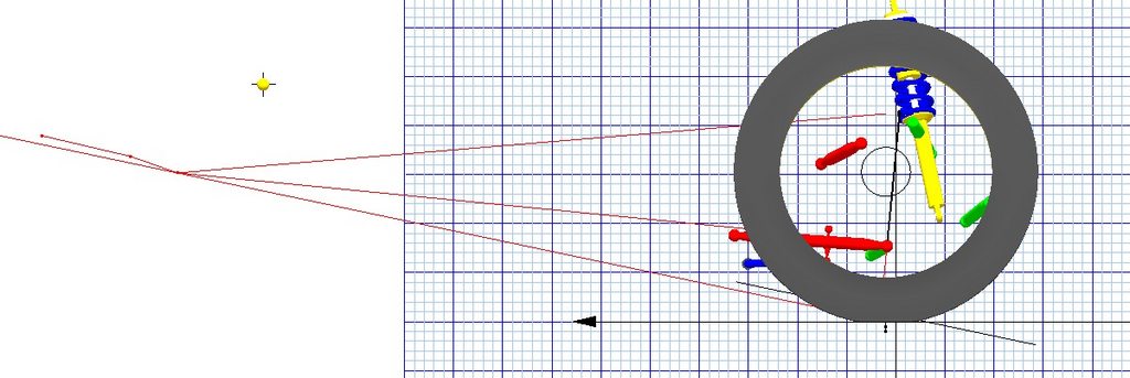 Unfortunately for 90's Nissans, we are stuck between two extremes. The S13 (and Z32/R32 for that matter), have a huge amount of anti-squat (somewhere around 180%), which means engine torque is very directly transferred to the tires, often shocking them into breaking traction earlier than ideal. The S14 and S15 (and R33/34), have a very small amount of anti-squat at standard height, but this quickly goes pro-squat when the car is lowered. This means the car squats excessively, changing the suspension geometry, reducing traction, and delaying the cars reaction to inputs to the throttle. Fortunately, the overwhelming aftermarket support for these vehicles have come up with some very nice solutions, which I will present below. Roll Center: Front roll center is determined by the angle of the lower control arms and the angle of the upper strut mounting points. These angles, drawn in space, determine the instant centers for the front suspension (instant centers are the points that the entire suspension moves around during body roll). Then take a line from each instant center to the middle of the tire tread on the opposite side, and where these lines intersect, there is your front roll center. Rear roll center (for our cars) is determined much like a double wishbone setup. Use the angles of the upper and lower control arms to determine the instant centers of the suspension. Then, just like the front, take a line from each instant center to the middle of the tire tread on the opposite sides. The intersection is your rear roll center.  Center of Gravity: The center of gravity is the point at which all the weight of the car is balanced. It's roughly the crank centerline in the front, and above the differential in the back. You can find out your exact CG by using scales, but that is beyond the scope of this article. Roll Couple: Roll couple is the distance between your center of gravity and roll center. This is the reason that lowered cars have more body roll. The roll center moves lower (due to the change in angle of the suspension arms), while the center of gravity is only lowered as much as the body of the car. This makes the distance between the two longer, thus the roll couple longer, which gives the body more leverage on the suspension. I'm sure we all know how much of a difference leverage can make. You actually want your roll center just under your center of gravity. Part II: Roll Center Adjustment Here are the things you can use to adjust roll center: 1. Use a ball joint with a shank that is longer, thereby spacing the pivot point at the knuckle farther down. The only ball joints that I’ve seen that actually have a longer shank are Sunline Racing, Moonface, and Nagisa auto: Nagisa:  Beware of "Roll Center Adjusting ball joints" that just space the ball joint up. The ball joint shank needs to be longer. Nagisa has a good illustration (bad on the left, proper on the right):  The above method is only so effective. Due to the angle of the ball joint, using a long shank increases ackerman, and at about 20mm of correction, the lower control arm starts running into the brake rotor. Dan at Parts Shop MAX made a nice diagram showing how the ackerman change happens: 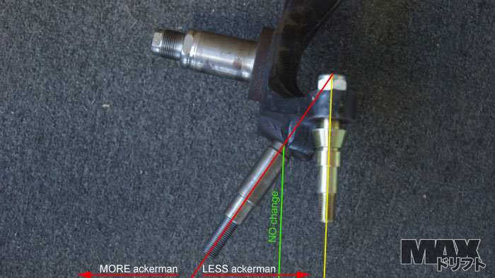 2. Purchasing aftermarket lower control arms that have roll center adjusting heim joints and shanks. There aren't a whole lot of arms that offer more than 10-15mm of correction because of brake rotor clearances. Ikeya Formula has some correction, and PSM has a 5mm fine adjustment spacer. 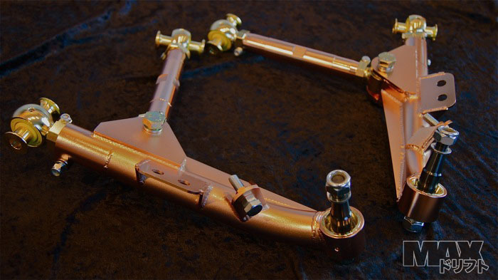 They've updated these with bent tension rods for more steering clearance:  PSM's limit break (longer) LCA:  And GKTech's latest chromoly FLCA's. You can order these with 20mm longer shanks.: (Image courtesy of swapmysilvia.com)  These are some nicely engineered pieces, and they fail just as they should when running into things.  3. Modifying the pickup points on the knuckle (usually by creating a whole new knuckle), dropping them lower. Also, raising the hub location in the knuckle, which effectively creates a ‘drop knuckle’; a knuckle that lowers the car while keeping roll center similar. Some of the kits actually combine both ways, raising the hub, and lowering the pickup points. Driftworks makes drop knuckles, 45mm in the front, and 50mm in the rear. The rears have urethane bushings for the control arms:  Stock knuckle:  Driftworks knuckle:  R-chassis front Driftworks with 20mm correction:  They just released their new Geomaster V3, which was collaborated on with Wisefab. Now with 50mm of front correction and revised steering geometry. Front knuckle has drift and grip settings and the rear now has sphericals.    Parts Shop MAX forged pro knuckle:   And their new ‘trailing knuckle’ with increased caster trail and adjustable ackerman:   Parts Shop MAX latest forged 25mm drop knuckle with spherical bushings: 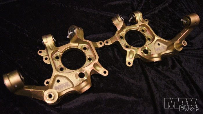 And their ‘toe control’ brackets, which allow you to dial in different levels of bump steer: 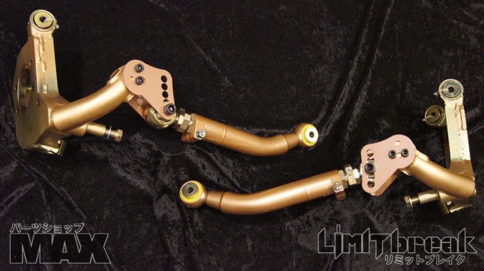 Here's a comparo shot between the Driftworks and PSM:  Wisefab now has their s-chassis V2 kit out, packed with features. Double shear pickups for LCA and tie rod, camber/caster top hats, 56+mm of roll center correction, trailing knuckle design, adjustable ackerman, and a rack relocation kit that moves your rack 46mm forward. 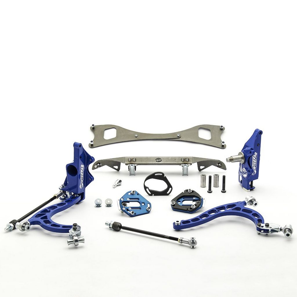  Wisefab's rear kit, with all new geometry for better rear grip:   GKTech now has three different variants of their front knuckle with 50mm of correction. They have grip, grip/drift, and pro drift versions, each with their own characteristics:    They also have this cool diagram of the different steering geometries of their knuckles/kits:  And this very informative link about all the geometry associated with their knuckle and why they designed it the way they did. https://au.gktech.com/news/gktech-s-...eering-knuckle GKtech also offers R-chassis knuckles which can be used on the Z32. 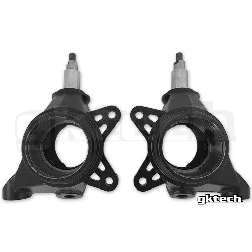 Photo courtesy of Chris York: 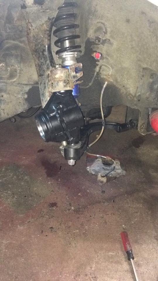  And their rear 40mm rear knuckle with new kinematics for better camber and to curves and corrected anti-squat. This knuckle is also significantly lighter than stock: 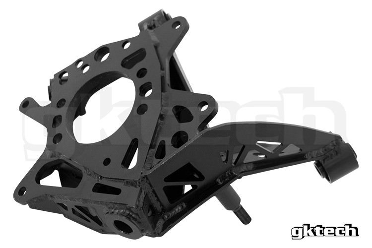   And GKtechs bolt on knuckle adapter with 40mm of correction (now in forged steel instead of aluminum):  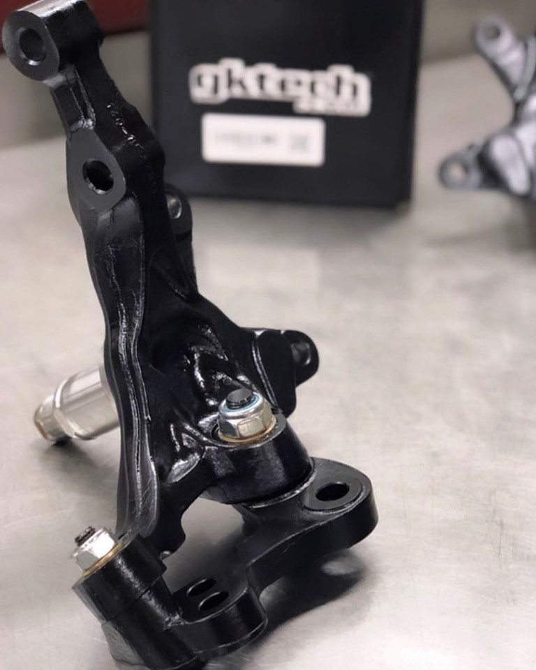 Track Day Performance has a billet aluminum front suspension kit with 70 or 100mm of correction (No longer available).   And their rear kit (I don't have shots of the arms that come with  ) ) Heatmaker knuckles offer 60mm of correction:  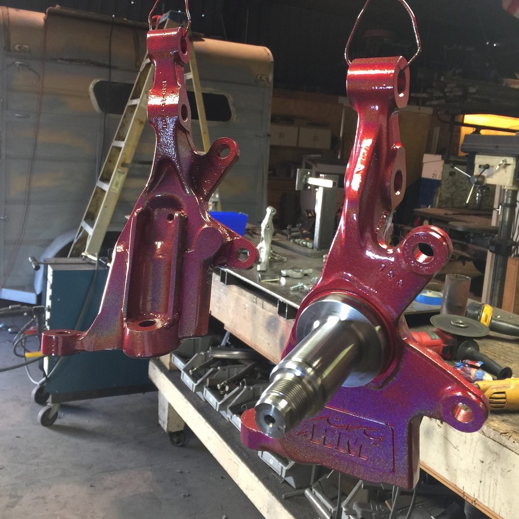 6. You can move the whole subframe up, correcting the suspension geometry much like the modified knuckles. SPL’s subframe adjusters (which can be either set for stock, or raised for ride height correction). These also can be ordered in an offset pattern, so you can mount a S14/15 subframe in your S13:  PSM's slip fit risers (Installing these was cake):  NOTE: Raising the subframe also increases anti-squat. SPL provides a very good link on how pushing the Subframe affects anti-squat and roll center: http://splparts.com/instructions/SPL_SSB_S13C.pdf Last edited by PoorMans180SX; 05-27-2021 at 07:28 AM.. |
|
|

|
| Sponsored Links |
|
|
#2 |
|
Zilvia.net Advertiser
 Join Date: Nov 2005
Location: Michigan
Age: 33
Posts: 5,430
Trader Rating: (16)
           Feedback Score: 16 reviews
|
This is the roll center, suspension pickup, and steering angle modification thread.
Part III: Steering Angle Modification
Let's talk about steering geometry for a bit. There's a lot to consider when you're picking out parts for steering angle. We now have tons of options. When I first made this thread, it was pretty much cut n' shut knuckles or Driftworks. Ackerman in the steering: In layman's terms, ackerman is the steering angle difference between the right and left front wheels when turned. This has important implications in drifting and in road course work. When turning normally, the wheel to the inside of the corner turns a smaller circle than the outside one. This makes the ideal angle between the two different. In long sweeping corners, low ackerman is advantageous, while tight hairpins require more positive ackerman. Drifting has the same requirements, except there are situations where you are turning much farther than a road course car would be. Too much ackerman in high speed corners (or at high steering angles) means that the wheel with less angle is scrubbing, which slows the car down and increases tire wear. Too little ackerman in tight corners means the opposite, while turn-in speed is reduced and more input required. Basic image of ackerman reduction:  Now let's talk about steering axis inclination (SAI). This is also known as kingpin inclination or kpi, but since cars haven't had kingpins since the 30's, I feel like we should use the proper term. This is another thing that is very easily misunderstood, as the kinematics are quite dynamic throughout the steering range. For the purpose of our discussion, I'm going to talk about SAI as if it includes caster. By definition SAI is the angle of the suspension from the top mount of the shock through the ball joint when viewed from the front only, but since our cars are always going to have positive caster and our goal is to understand how the suspension angle effects the geometry throughout steering lock, it's easier to condense the two. Let's start with a car going around a track in standard racing fashion. Front camber while steering is determined by the SAI, and with positive caster, this means the outside wheel gains negative camber and the inside one positive. This is very beneficial in typical racing, as the outside wheel needs negative camber to offset body roll and tire deflection. This can obviously be adjusted so as to be optimal per setup. In drifting, quite the opposite is true. Countersteering into a corner means the lead wheel gains positive camber and the trailing negative, leaning the tires up on their edges and reducing contact patch. This effect also makes the steering want to self-center, as the car lifts in the front and the weight of the car wants to push the steering back to center. There is a balance to be struck here, and it largely depends on how the driver likes it. Professional drifting has moved towards reduced caster and therefore flatter contact patch at big steering angles. This increases controllability at speed and allows for effective braking. A large number of grassroots drivers prefer standard or even increased caster though, this makes the car self-steer more aggressively, and can help with hucking big backwards entries. The front tires will start to slide and then smoothly return when correcting, which makes the entry look much smoother. Caster trail: There is also ‘caster trail’ to consider. With the need for larger front contact patches and less static caster, the steering can lack feel and lead to a driver having to steer excessively, pulling the wheels away from lock and manually returning the wheels to center. By setting the hub farther back in the knuckle (front to rear), the caster trail can be increased, meaning that the steering still wants to return to center even at low static caster angles. I borrowed this image from interia-ms.com as it illustrates it nicely:  PSM, Wisefab, and TDP, and Driftworks all have knuckles with increased caster trail available. GKtech has one in development. PSM has a good side-by-side so you can see the difference. Trailing knuckle on the left and standard on the right. 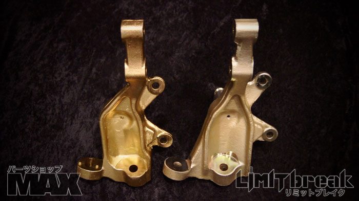 With the increased prevalence of reducing static caster angles, companies have developed offset strut tops. This allows the tension rod to be used as a fine adjustment, and keeps the wheel more centered in the well. GKtech has two versions, one that you need to cut the top of the tower to fully utilize, and another thicker one that bolts in with no modification:   TDP's is similar to the second GKtech: 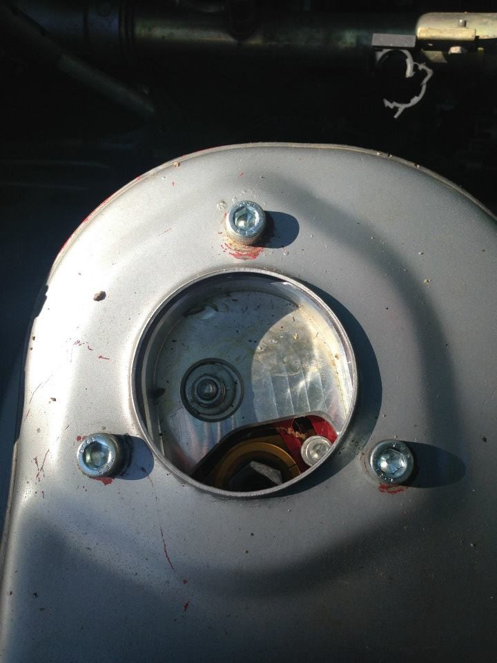 PSM has one available for their coilovers specifically:  Wisefab was pretty much the originator of the idea, first with their fixed position "non-FD legal" tops, and then with their adjustable "FD legal" variant. Fixed position is pictured above in the picture of the full kit.  There are several ways to go about getting more steering angle; like tie rod spacers, steering rack spacers, and obviously modified or new knuckles. Classic steering angle spacer: 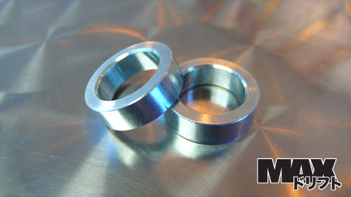 Big steering angle spacer:  There have been plenty of companies that have come and gone over the years, making their own version of modified or new knuckles for the s-chassis: Naoki Nakamura's now infamous B-knuckle:   MA-Motorsports modded (no longer available):  Billspeer 555 Knuckle (no longer available): 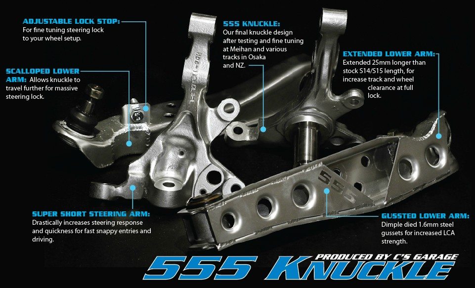 Abercrombie (no longer available):   Driftworks claims 65 degrees of steering lock on their V2 Geomasters:   Parts Shop MAX has 65+ degrees of steering lock:   Wisefab also claims 65 degrees of lock:  And their ackerman adjustment spacers:  Track Day Performance claims up to 70 degrees of lock (No longer available):  GKtech claims 70 degrees of lock with their V3 knuckles and LCA combo:  Overcentering: Another thing that's rarely mentioned when talking about all this increased angle, is the tendency of the steering rack to go "over center". This is where the angle of the tie moves farther than parallel with the steering arm of the knuckle Image borrowed from interia-ms.com  This can be alleviated a couple ways: 1. Moving the steering rack forward:   2. Spacing the tie rods farther forward, using spacers like these Driftworks ones: Version 2:  Or the Parts Shop MAX version:  and GKTech: 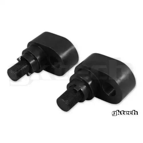 These do the same thing as the eccentric bushings, but have more correction. And there have been talks of solid steering rack bushings warping and becoming loose. NOTE: These could put stress on your rack that it was not designed for. 3. Using Parts Shop MAX steering rack eccentric bushings:   Dan gathered some interesting information about how moving the rack forward effects ackerman angle:  4. Once you're using high-clearance tension rods/control arms, you'll need to worry about your trailing wheel hitting your sway bar. There are two solutions for this: The GKTech high clearance sway bar:    And the Bink Industries high clearance bar, available in street and Pro versions, and residing on quite a few Pro and Pro-am cars. These come with endlinks, D-bushes, and brackets. Street:    Pro:    Parts Shop Max has a high-angle sway bar as well. Comes with brackets, bushings, and locks.   Depending on your knuckle/LCA/tie rod end combo, you're probably going to need longer tie rods. Here's a nice list of lengths: Inner: M12x1.25: 11.10" - '89-'94 240sx (S13) M14x1.5: 11.37" - '95-'98 240sx (S14) 11.42" - '94-'99 Maxima (A32) 11.42" - '96-'99 I30 (A32) 12.00" - '97-'01 Q45 (FY33) 12.00" - '01-'06 Q45 (F50) 12.91" - '99-'03 Maxima (A33) 12.91" - '00-'04 I30 (A33) 13.30" - '03-'08 Maxima (A34) 9.25" - PSM Short 11.73" - PSM Medium 13.93" - PSM Long 14.50" - GKTech Outer: M12x1.25: 3.88" - '89-'94 240sx (S13) M14x1.5: 3.63" - '95-'98 240sx (S14) 5.00" - '88-'94 Maxima (J30) x.xx" - '94-'99 Maxima (A32) Let's discuss.
__________________
Build: http://zilvia.net/f/showthread.php?t=643065 Friends don't let friends buy knock-offs. Last edited by PoorMans180SX; 05-27-2021 at 07:27 AM.. |
|
|

|
|
|
#7 |
|
Zilvia.net Advertiser
 Join Date: Nov 2005
Location: Michigan
Age: 33
Posts: 5,430
Trader Rating: (16)
           Feedback Score: 16 reviews
|
You're welcome guys. This is something I kind of geek out on, so I thought I would contribute to the community.
Here's a question I have. It seems like if you did all the roll center adjustment you possibly could, you could actually put the roll center above stock, even on a slammed car. Anyone know if this is detrimental to suspension performance or not? Maybe it's advantageous?
__________________
Build: http://zilvia.net/f/showthread.php?t=643065 Friends don't let friends buy knock-offs. |
|
|

|
|
|
#8 |
|
Guild of Skullduggerous Intent
 |
There various thread on NRR already dealing with these topics
one of the more extensive ones: Roll Center.....again - Nissan Road Racing Forums good topic, I've seen the suspension set up of a Porsche GT3 Cup car and it floored me just like our cars they're McPherson struts up front with a independent arms in the rear I want that in my car |
|
|

|
|
|
#10 |
|
Nissanaholic!
 Join Date: Mar 2007
Location: SOCAL/NORCAL
Age: 32
Posts: 1,867
Trader Rating: (12)
   Feedback Score: 12 reviews
|
im really sure there is a ton of info here but im an uber noob on suspension and dont really nkow whats going on in some of these pictures. maybe a introductory thread that leads up to this one would be sweet!!
__________________

|
|
|

|
|
|
#11 | |
|
Zilvia.net Advertiser
 Join Date: Nov 2005
Location: Michigan
Age: 33
Posts: 5,430
Trader Rating: (16)
           Feedback Score: 16 reviews
|
Quote:
That's nice, but THIS IS ZILVIAAAAA!!! haha. I wanted a thread on here, and I want to update it with the latest products and such, not just "this is how you could possibly do it". Thanks for a solid link though, I might steal some of their pics to make this thread better. Yeah, I might do that, but most of the general stuff is readily available and easy to find. This is the hardcore stuff.
__________________
Build: http://zilvia.net/f/showthread.php?t=643065 Friends don't let friends buy knock-offs. Last edited by PoorMans180SX; 12-24-2009 at 01:57 AM.. |
|
|
|

|
|
|
#12 | |
|
Post Whore!
 Join Date: Jul 2005
Location: LA
Age: 36
Posts: 3,402
Trader Rating: (19)
           Feedback Score: 19 reviews
|
Quote:
That's my thread on NRR - lots of ideas got shot down in there, haha. One of them was modifying the inner pick up point. You affect a lot more then just the roll center when you do it. There is more then enough room to drill a hole above the stock location and move the arm up a good inch. I was steered away from that by the guys on NRR though so I would listen to them. Also, my rear arms are corrected more then stock, I just don't have any spacers on them yet. You can see the slight angle difference from my toe arm and LCA. I should be able to get it mostly flat, but I've got to track down the proper spacers. Also, you don't necessarily want the roll center back to the factory location. The 240 wasn't exactly a performance monster from the factory. I haven't done enough research to say what might be optimal...so going for straight LCAs is a good goal for now. I'll be able to fine tune it as I drive it.
__________________
 Instagram - SJKnoop |
|
|
|

|
|
|
#13 |
|
Zilvia Addict
 Join Date: Jan 2007
Location: Up and Down! California
Posts: 878
Trader Rating: (8)
 Feedback Score: 8 reviews
|
Oh wow this thread has definitely been one ive been waiting for/ planning to make. Ive been researching this stuff forever too but it seems like you have covered a lot of it! NICE JOB!
|
|
|

|
|
|
#14 |
|
Zilvia Junkie
 Join Date: Jan 2005
Location: gloucester, VA
Age: 42
Posts: 517
Trader Rating: (6)
      Feedback Score: 6 reviews
|
I did all the mods to 95KA-turbo's suspension. Let me tell you that this wont be an easy install. All the parts that where ordered had very close tolerences. I had to grind down/sand a few things to get it to work. We dont now how its all gonna work out because we are in the R&D mode right now. Once we get it set the way we want it we will report back here with updates. Hope fully in about 2 months when the car is rolling under its own power.
Danny
__________________
1994 FD3S Drift // 945garage //  sumospeed.com sumospeed.com
|
|
|

|
|
|
#15 |
|
Premium Member
 Join Date: Jan 2005
Location: Cali
Age: 53
Posts: 1,371
Trader Rating: (29)
           Feedback Score: 29 reviews
|
Very informative! Thank you very much for putting this together.
I am interested to see how these mods are affected by the sactioning bodies. Last I read is that you could only move your pick up points 1" in any given direction. |
|
|

|
|
|
#16 | |
|
Guild of Skullduggerous Intent
 |
Quote:
the griggs stuff that was posted there haunts me, specially their 3 piece knuckle.   |
|
|
|

|
|
|
#17 |
|
Nissanaholic!
 Join Date: Dec 2008
Location: Upstate NY
Age: 41
Posts: 1,700
Trader Rating: (15)
 Feedback Score: 15 reviews
|
I modified the stock lowers (rear and front) to acccept 3/4" spherical bearings and monoball studs for roll center adjustment. No pics of the fronts yet. But I had to ream the uprights to a 7° GM taper for the studs to work.
  |
|
|

|
|
|
#18 | |
|
Nissanaholic!
 Join Date: Dec 2008
Location: Upstate NY
Age: 41
Posts: 1,700
Trader Rating: (15)
 Feedback Score: 15 reviews
|
Quote:
|
|
|
|

|
|
|
#19 | |
|
Post Whore!
 Join Date: Jul 2005
Location: LA
Age: 36
Posts: 3,402
Trader Rating: (19)
           Feedback Score: 19 reviews
|
Quote:
I personally do not 100% understand how moving the inner point up effects the motion of the tension rod - I mean it should technically do the same thing as lowering the outside out point. I was assured that it would put some unforeseen forces on the arm that would screw up everything. I am not an engineer - perhaps Def will come in and explain. It is stated in that NRR thread. I got mad because no one would explain it to me at first, then I got a kind of half-ass explanation from a few people.
__________________
 Instagram - SJKnoop |
|
|
|

|
|
|
#20 | |
|
Post Whore!
 |
Quote:
And therein lies the problem, if you move the FLCA pickup points up, because the rack would also need to go up along with the FLCA pickup points so that the tie rods' arc and the FLCAs' arc will stay in sync. If not, the car will get some nasty bumpsteer. that pretty much cannot be corrected due to the 2 having totally different arcs. Edit - if you move the FLCAs' pickup point, then the T/C rods' pickup points will have to move up the same amount as well. Think about it. If you moved the FLCAs' pickup points by an inch, and if you flattened it, the T/C rods will no longer be parallel to the FLCAs anymore. They'd be pointing up in order to meet the FLCAs, and probably no way for them to bolt up to the FLCAs because of the angle that they're in, so they will need to be moved up an inch as well. |
|
|
|

|
|
|
#21 |
|
Nissanaholic!
 Join Date: Dec 2008
Location: Upstate NY
Age: 41
Posts: 1,700
Trader Rating: (15)
 Feedback Score: 15 reviews
|
Well corrected to a point with a bumpsteer kit but they can only correct so much before moving the whole rack up is the next option. Which in my case with the LSx is a no go, there is about 1/16" between the rack and the oilpan.
|
|
|

|
|
|
#22 | |
|
Guild of Skullduggerous Intent
 |
Quote:
the traction rod connects to a perpendicular brackets and it's position can be adjusted with round spacers of various lengths held with a bolt the lower control arm is a two piece design cast in aluminum - shims can be stacked near the crossmember bushing held by two bolts to adjust track and probably quick alignment changes. |
|
|
|

|
|
|
#23 |
|
Post Whore!
 Join Date: Jul 2005
Location: LA
Age: 36
Posts: 3,402
Trader Rating: (19)
           Feedback Score: 19 reviews
|
Ah that's right, it makes sense to me again. I had forgotten how I had to think of it to make sense, haha.
By moving the inner point up, you are making the LCA angle better but the tension rod angle worse. By moving the outer point down you are making your tension rod angle and LCA angle better at the same time. The tie rod angle can be fixed with spacers and heim joints, much like the spherical bearings and spacers used for the roll center. Here is an interesting article that somewhat explains why one type of roll center isn't ideal for everyone/every car. Unfortunately they're talking about stock cars and they have completely different suspension set ups then we do: Accelerating Performance: Roll Center Magic
__________________
 Instagram - SJKnoop |
|
|

|
|
|
#24 |
|
Post Whore!
 |
The point is, the tie rods' pick up point will differ from the FLCAs' pick up point if you move just the FLCAs. One will be higher than the other, which will cause different arcs.
When 2 arms have the same arc, you can correct for stuff much easier. When you have 2 arms that have different arcs now, it is much harder to correct for that type of stuff.... |
|
|

|
|
|
#25 |
|
Post Whore!
 |
Loving this thread, and the work that went into making it. True, this is more of a NRR-type thread (that site is awesome, btw, I just got turned on to it recently), but I love that the community is moving towards real performance modification, not just 'this looks cool', or 'check out what i did for free'.
Makes me proud  Luke (Blu808) and I have been talking over making some CNC aluminium LCA's since we both have access to CNC machines and I have all the heim joints. We just need to come up with a final design (which has to address roll center, bump steer if possible, big angle kits, etc) ~ maybe this thread will help.
__________________
Jordan Innovations has a new web site! www.JordanInnovations.com -- All your favorite FD Pro Drifters love it, trust me -- www.JordanInnovations.com |
|
|

|
|
|
#26 | |
|
Guild of Skullduggerous Intent
 |
Quote:
we're in a similar situation, we can make just about anything but it's not very useful without a well thought out design any automotive/mechanical engineers in socal that are serious about making cool shit, get at me  |
|
|
|

|
|
|
#27 | |
|
AFC #1
 Join Date: Oct 2003
Location: 昨晩あなたのお母さんの家
Posts: 20,181
Trader Rating: (3)
           Feedback Score: 3 reviews
|
Quote:
It's what silk road does on their time attack car. I wish I had more data on it but have only seen one article.
__________________
Comments should be taken as Opinions not as Statements of Fact 
|
|
|
|

|
|
|
#29 | |
|
Zilvia FREAK!
 |
Quote:
To add to this thread, adding additional roll center adjustment for the rear (ie lower control arm) could possible hurt the rear geometry of the other arms. The best fix would be to replace the rear spindle to ensure that the arc movements remain unaltered.
__________________
.25 till 3 |
|
|
|

|
|
|
#30 |
|
Post Whore!
 Join Date: Jul 2005
Location: LA
Age: 36
Posts: 3,402
Trader Rating: (19)
           Feedback Score: 19 reviews
|
Definitely, a new spindle out all around is by far the best method to correct everything properly. An adjustable control arm on top of that would be great, then EVERYTHING could be adjusted.
__________________
 Instagram - SJKnoop |
|
|

|
 |
| Bookmarks |
| Tags |
| anti-squat, best thread ever, kpi, roll center, steering angle, suspension |
| Thread Tools | |
| Display Modes | |
|
|